8145-20 Defrost Timer Wiring Diagram: The Appliance Fix! 8145 20 defrost timer wiring diagram
Alright folks, let's talk about something near and dear to any homeowner's heart: keeping our fridges running smoothly. We've all been there, staring into a freezer slowly accumulating a thick layer of frost. It's inefficient, annoying, and eventually leads to a full-blown defrosting operation, which nobody enjoys. That's where the unsung hero, the defrost timer, comes into play. Specifically, let's peek at the Paragon 8145-20 defrost timer wiring diagram. It might sound intimidating, but with a little patience and a good diagram, it's manageable even for the moderately handy among us.
Paragon 8145 20 Defrost Timer Wiring Diagram
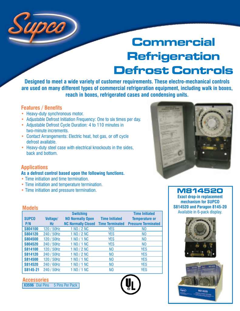
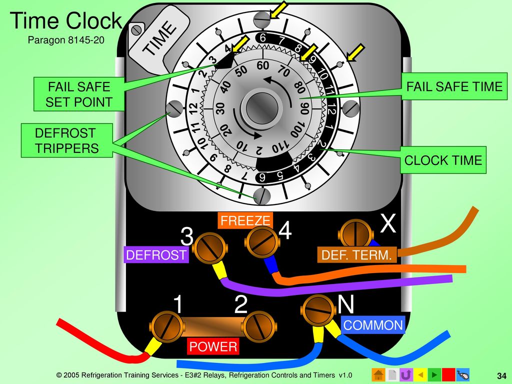
Now, at first glance, these wiring diagrams can look like a plate of spaghetti. But trust me, it’s just a matter of breaking it down. What you're seeing here is a visual representation of how the various components – the timer motor, the defrost heater, the thermostat – all connect together. Note the different colored wires and their corresponding terminals on the timer. These colors are your best friends when tracing the circuits. The key is to identify the input power source (usually marked as L1 and L2), the load connection to the compressor and the defrost heater, and the connection to the defrost termination thermostat. This thermostat is crucial because it prevents the defrost heater from overheating and potentially damaging your freezer. It’s the safety net in the system. Before diving into the actual wiring, always remember to disconnect the power! Safety first, people. Nothing is worth risking a shock.
Wiring diagram for Paragon 8145-20 defrost timer

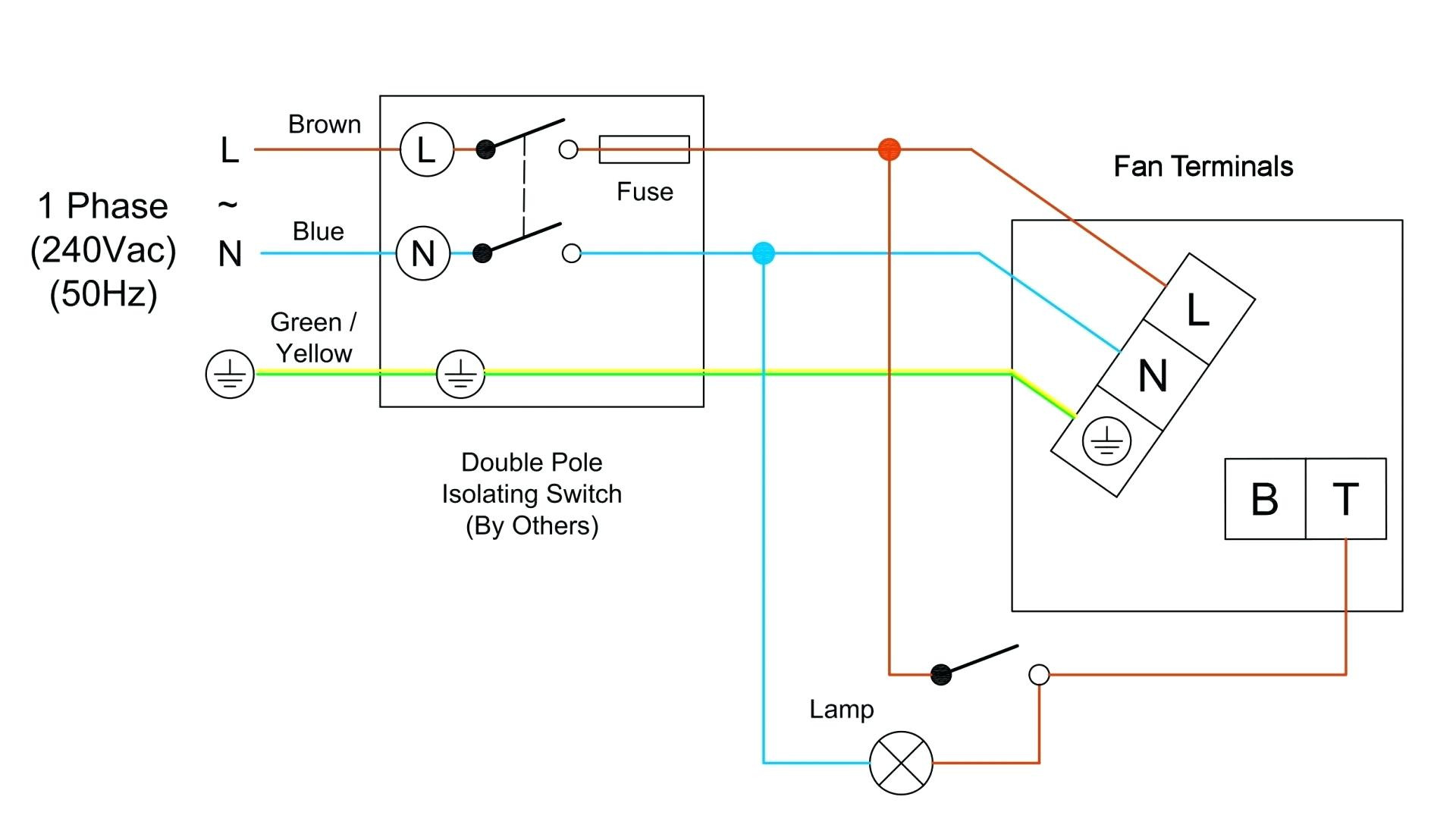
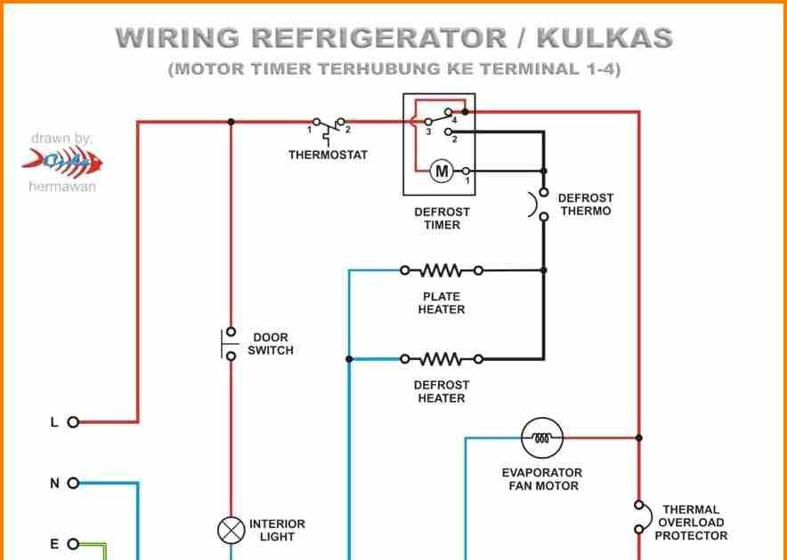
This diagram presents a slightly different perspective, and sometimes seeing things from another angle can really help clarify the process. Notice the common connection points and how the timer cycles between the cooling and defrost modes. These timers usually operate on a timed cycle, such as every eight hours, initiating a defrost cycle that lasts for a set duration, typically around 20-30 minutes. Understanding this cycle is essential for troubleshooting any issues. If your freezer is icing up constantly, even with the timer seemingly functioning, it could be a faulty defrost heater, a malfunctioning defrost thermostat, or even a blocked drain line preventing the melted ice from escaping. A little detective work with a multimeter can help pinpoint the culprit. Remember, these diagrams are guides. Your specific refrigerator model might have slight variations. Always consult your refrigerator's service manual, if available, to ensure compatibility. Replacing a defrost timer can save you a service call, but only if you're comfortable and confident in your abilities. If not, calling in a qualified appliance repair technician is always the wisest choice. A little knowledge and a careful approach can keep your fridge running efficiently for years to come, saving you both food spoilage and headaches.
If you are searching about How to Wire a Defrost Timer: 8145 20 Wiring Diagram Guide you've came to the right place. We have 25 Images about How to Wire a Defrost Timer: 8145 20 Wiring Diagram Guide like Paragon Defrost Timer 8145 20 Wiring Diagram » Wiring Today, Paragon Defrost Timer 8145 20 Wiring Diagram - Wiring How and also Paragon 8145 20 Defrost Timer Wiring Diagram - Wiring Diagram. Here you go:
How To Wire A Defrost Timer: 8145 20 Wiring Diagram Guide
 design1systems.com
 Paragon Defrost Timer 8145 20 Wiring Diagram
.jpg?strip=all) www.wiringhow.com
www.wiringhow.com Paragon 8145 20 Defrost Timer Wiring Diagram - Wiring Diagram
wiringdiagram.2bitboer.com 8145 20 Defrost Timer Wiring Diagram - CrawfMinahal
 crawfminahal.blogspot.com
 Paragon Defrost Timer 8145 20 Wiring Diagram
 www.circuitdiagram.co
 Wiring Diagram For Paragon 8145-20 Defrost Timer
 signalwires.com
 Paragon Defrost Timer 8145 20 Wiring Diagram - Wiring How
 www.wiringhow.com
 Guide To Wiring A Paragon Defrost Timer
 diagramio.com
 Wiring Diagram For Paragon 8145-20 Defrost Timer
signalwires.com 8145 20 Defrost Timer Wiring Diagram - CrawfMinahal
 crawfminahal.blogspot.com
 8145 20 Defrost Timer Wiring Diagram - Organicid
 organicid25.blogspot.com
 Wiring Diagram For The 8145-20 Defrost Timer
 allwiringsketch.com
 Wiring Diagram For Paragon 8145-20 Defrost Timer
 signalwires.com
 8145 20 Defrost Timer Wiring Diagram Schematic And Wiring Diagram
 www.aiophotoz.com
 Wiring Diagram For Paragon 8145-20 Defrost Timer
 signalwires.com
 8145-20 Wiring Diagram
 wiringall.com
 wiring diagram paragon timer orbis defrost volts specifications uni hz line series part no schematron
Paragon Defrost Timer 8145 20 Wiring Diagram
 www.circuitdiagram.co
 8145-20 Defrost Timer Diagram
 stewart-switch.com
 Wiring Diagram For Paragon 8145-20 Defrost Timer
 signalwires.com
 Paragon 8145 20 Wiring Diagram
 www.mikrora.com
 wiring diagram supco 8145 paragon relay defrost timer starter compressor freezer
Paragon Defrost Timer 8145 20 Wiring Diagram » Wiring Today
 www.wiringtoday.com
 Defrost Timer Schematic Diagram
 axiom-northwest.com
 Paragon 8145 20 Defrost Timer Wiring Diagram
 schematron.org
 paragon defrost timer wiring diagram cycle diagrams adjustable duration defrosting heat minutes electric series
8145-20 Defrost Timer Wiring Diagram
 axiom-northwest.com
 Precision Defrost Timer Wiring Diagram Unique Clock And Freezer To
 www.mikrora.com
 wiring diagram timer precision defrost
Wiring diagram for paragon 8145-20 defrost timer. Paragon defrost timer 8145 20 wiring diagram. Paragon 8145 20 defrost timer wiring diagram